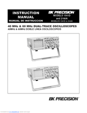
Bk Precision Oscilloscope 2160 Service Manual
View and Download BK Precision 2190B instruction manual online. DUAL-TRACE OSCILLOSCOPE BK PRECISION. Authorized B+K Precision service contractor. Reddit: the front page of. I have an old 20 Mhz BK Precision 2160 Oscilloscope that needs calibration or repair I'm not sure. I can't find a service manual for.
Hello My oscilloscope is in desperate need of repair. I work mainly in pro audio electronics and have no experience in oscilloscopes repair. So it would be great to have some of you help, if you can spare the time. My unit is branded UniVolt OS-3062, although I was able to find it's just a re-brand and it's the same unit as the BK Precision 2160, Elenco S-1360 and Pintek PS-605. There's diferent BK Precision 2160 models, theres the 2160, 2160A and the 2160C.
I guess my unit it the 2160, as I was able to get some service docs for the 2160A and the PCB's layouts and component numbering are different. The unit powers up, but there's only a fixed Dot in the middle of the screen. I guess that means that both the Horizontal and Vertical circuits are not working properly. I would like to start by checking the PSU voltage rails but without the schematics or service manual it's a bit hard since I dont see any test points or voltages silkscreened on the PCB's.
Does anyone have the Service Manual for the BK Precision Model 2160? Tried to contact BK Precision, Elenco, Pintek and the only Univolt supplier I found online and got no response. Also I searched quite a bit on the Web for service manual/servicing info and schematics for these models and had no luck.
I guess I will have to try to measure the voltage rails using the 2160A schematic hoping that the schematic is similar. Any tips and thoughts are welcome. Thank you so much I got that manual and also the BK 2125 Service Manual that is available on the same site and the PSU's dont match my unit. I also got a Schematic for the Pintek PS-605 and is doesn't match my unit but it matches the BK 2160A. (this PSU uses 7812, 7912 and 7805 regulators) I was able to get the Service Manual from BK Precision for the '2160' unit and although it's an 1993 schematic it also doesn't match my unit. This a nice and detailed Service Manual, I got the Service Manual for the older Elenco S1360 and finally the PSU schematic corresponds to my Oscilloscope. Unfortunately this Service Manual is the worst of the bunch I got.
No parts Lists, some small mistakes, Schematics dont show values for components and theres no parts list to identify them. Anyway it's much better than nothing so with this I was able to start tracing. Here is the PSU Schematic: I Measured all the voltages at the transformer secondary and every value is spot on.
Multimeters

Replaced all the PSU Electrolytic caps with new Panasonic 105º Replaced BD901 and BD902 Bridge rectifiers Replaced IC's U901 and U902, these are MC4558 opamps Unsoldered Q901, Q902,Q903 and Q904 and verify them with my Atas DCA Pro, all the transistores measured good. Soldered them back on Tested all the PSU diodes, all tested well Problems: After the BD901 regulator I'm measuring +-15v instead of +-18.

Collector of Q902 I'm measuring +1.7v instead of +12v. Collector of Q903 I'm measuring -0.9v instead of -12v. All the other circuit boards are disconnected from the PSU board. Any idea of what might be causing this?
The only thing that I didnt had time to do today was measuring the resistors one by one because I have to lift one leg up, visually they look fine. Theres one strange thing with the DB901 bridgr rectifier.
I measure it with the + and - legs in the air so it was not connected to the rest of the circuit. I have 16VAC coming from the transformer, after BD901 I'm measuring + and - 14VDC, thats really strange shouldn't the votage after rectification go up by an 1.414 ratio? I changed the Bridge Rectifier for a new one and the same happens.
Hello I was not getting anywhere with the +-12V rails problem so I decided to convert this rails to use the 7812 and 7912 regulators like in the updated revisions of this PSU. Here is the present PSU schematic The +-12 rails are spot on now.
Voltages on the other 2 rails are a bit lower than the correct value I'm measuring 117V instead of 145V and 3.6V instead of 5V Something is strange with the 'High Voltage multiplier' of the Second Anode Supply (the one that has the suction cap and 12Kv), this is a Black rectangular plastic box with some sort of Red epoxy potting material. As soon as I power the unit this box makes some crackling noise, when I turn the power off the box still crackles for 1 to 3 seconds and then stops. Here are some pictures and symbols of the component in question, the red wire that come out of it it's the wire that has the suction cap in it's end and connects to the second CRT anode.
What might be the cause of the crackling noise? Arching inside the multiplier box? Excessive voltage on the multiplier's input? The multiplier is shot? Quote Something is strange with the 'High Voltage Rectifier' of the Second Anode Supply (the one that has the suction cap and 12Kv), this rectifier visually is a Black rectangular plastic box with some sort of Red epoxy potting material. As soon as I power the unit this box makes some crackling noise, when I turn the power off the box still crackles for 1 to 3 seconds and then stops.
What might be the cause of the crackling noise? Arching inside the rectifier box? Excessive voltage on the rectifiers input? The rectifier is shot? CRT still works even with this noise going on, although I only turn it on for some seconds because Im afraid at the moment that I might be damaging something else.
Hello everyone, I'm still trying to fix my scope, unfortunately photobucket removed my photos from this thread, but I will try to fix the picture links using another pic hosting site. I was finally able to fix all the voltage rails. I was able to get a another schematic of the PSU that has the components values written (the old one didnt have) and one resitor had the worng value. Replaced that and the 145VDC rail is fine now. So I have +12V and -12, 5V and 145V all spot on. I connected the unit and at least the CRT doesn't work, so the scope circuit may be working or not but it's impossible to tell without the monitor. When I turn the unit on there's crackling audible noise coming from the CRTs voltage multiplier.
The voltage multiplier is a sealed circuit a plastic box filled with a kind of epoxy. I'm afraid of damaging more stuff, so I didnt leave it on for long. I will have now to ask help locally to someone experienced with CRTs because of the High voltages presented there. Any suggestions or advice are welcome thank you all so much. I met the TV Tech, he had a nice HV probe. We are all to measure all the voltages above 1KV. All those voltages were fine.
Even the 12KV voltage going to the CRT suction cap. The 145V rail measures 145v when not connected to the circuit but when I connect it to the circuit it drops to 26V.
So I have to check whats going on there. Maybe there's a problem with the circuit that load that rail. I have to check now whats going on there, maybe if I fix that the Scope is back to work again. I'm just happy that we were able to measure all the HV and that concluded that part of the circuit is working as expected.
